Vehicle Structures
Vehicle Structures
Summary
Vehicle structures are categorized into four main types: body-on-frame (robust, modular, used in trucks/SUVs), integral/monocoque (lightweight, high rigidity, standard in passenger cars), space frame (3D truss for high-performance/low-volume vehicles), and backbone (central tunnel design for sports/off-road cars). Each type balances weight, cost, stiffness, and safety. Body-on-frame uses a separate chassis and body, while monocoque integrates them. Space frames employ tubular lattices, and backbone designs rely on a central spine. Manufacturing methods vary—stamped/welded panels for monocoques, extruded/hybrid materials for space-backbone frames—with trade-offs in repairability, NVH, and crash performance. Industrial frames prioritize torsional stiffness via rigid side/cross member connections.
Learning Objectives
Compare the structural characteristics of body-on-frame, monocoque, space frame, and backbone chassis designs.
Explain the role of side members and cross members in industrial vehicle frame construction.
Analyze the trade-offs between torsional rigidity, weight, and manufacturing cost in different vehicle structures.
Evaluate the suitability of integral (unibody) construction for modern passenger vehicles.
Design a simplified chassis layout justifying material choices.
Purpose
The primary purpose of a vehicle’s structure is to provide a rigid and durable framework that supports all mechanical components, systems, and payload while maintaining structural integrity under various dynamic and static loads encountered during operation. These loads include gravitational forces, acceleration and braking stresses, cornering forces, road-induced vibrations, and potential impact loads in the event of a collision.
Additionally, the vehicle structure must ensure occupant safety by effectively managing and distributing energy during crashes, while also contributing to overall vehicle performance, stability, and fuel efficiency through optimized weight distribution and aerodynamic design. The structural design must balance strength, stiffness, and lightweight construction to meet safety regulations, durability requirements, and performance standards.
Types
Vehicle structures can be broadly categorized into four main types (Malen 2011): body-on-frame, integral, space frame, and backbone. Figure 1.1 shows an example of each type. Each type has distinct design philosophies, advantages, and applications. Each type is chosen based on vehicle requirements, balancing factors such as weight, cost, safety, and performance. Table [tab:structure_comparison] summarizes the features of each structure type.
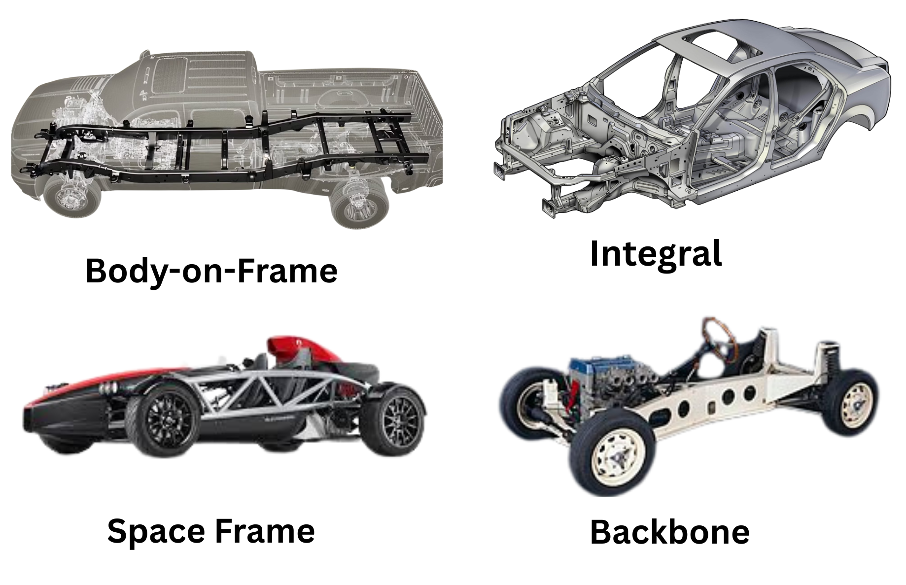 Types of vehicle structures.
p3cm >p2cm >p2cm >p2cm >p2cm
Feature & Backbone & Space Frame & Monocoque & Ladder Frame
Feature (cont.) & Backbone & Space Frame & Monocoque & Ladder Frame
Weight & Moderate & Lightweight & Lightest & Heaviest
Torsional Rigidity & Good & Excellent & Excellent & Poor
Bending Rigidity & Good & Good & Excellent & Fair
Manufacturing Cost & Low-Moderate & High & Moderate-High & Lowest
Production Volume & Low-Medium & Low & High & Medium-High
Crash Safety & Requires add-ons & Good & Best & Poor
Repairability & Good & Excellent & Difficult & Easiest
Drivetrain Integration & Excellent (RWD/AWD) & Good & Good & Excellent
NVH Characteristics & Fair & Good & Best & Poor
Typical Applications & Sports cars, off-road & Supercars, luxury & Passenger cars & Trucks, SUVs
Body-on-Frame (Ladder Frame)
The body-on-frame chassis is a traditional vehicle construction method where a separate, rigid frame structure supports all mechanical components while a non-structural body is mounted on top. This design, characterized by its ladder-like arrangement of longitudinal side members connected by transverse cross members, provides exceptional load-bearing capacity and durability, making it ideal for trucks, SUVs, and off-road vehicles. The frame absorbs all dynamic stresses from the suspension, powertrain, and payload, while the body primarily serves as a passenger compartment without contributing to structural integrity. Key advantages include modularity (allowing different body styles on the same frame), easier repairs, and superior towing/hauling capability, though it typically results in heavier weight and lower fuel efficiency compared to unibody designs. Modern implementations often incorporate high-strength steel or hydroformed sections to optimize strength-to-weight ratios while maintaining the design’s fundamental robustness.
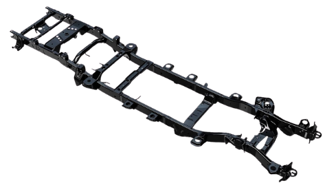 Frame structure showing side members and cross members arrangement.
Frame Construction and Components
Industrial vehicle frames are built around two primary structural elements: side members and cross members. The side members are longitudinal beams that form the main structural backbone of the frame, while cross members are transverse beams that connect the side members, ensuring structural integrity. The rigidity of the connection between these components is critical, as it determines the frame’s ability to resist torsional forces—particularly those applied along the vehicle’s longitudinal axis. Since industrial vehicles often operate under heavy loads and rough conditions, the frame must efficiently distribute stresses while maintaining stability.
Side Member Design
Side members are designed with varying widths to accommodate different vehicle components. Narrower sections are typically positioned where steering mechanisms and twin-wheel assemblies are located, while wider sections provide the necessary space for engine installation and driver cabin mounting. Additionally, the side members are tapered in elevation to allow sufficient suspension travel for the rear wheels—a crucial feature given the wide range of payload capacities these vehicles must handle. This tapered design ensures that the frame can flex appropriately under load without compromising structural integrity.
Cross-Section Design
The side beams usually feature a C-shaped cross-section, which, while not ideal for torsional stiffness, offers significant manufacturing advantages. This open-section design simplifies fabrication from high-strength steel sheets, reduces production costs, and allows for easier bending and shaping. To enhance rigidity in critical areas, reinforcements such as additional C-beam sections, platbands (reinforcement plates), or localized structural modifications are often applied. These reinforcements help counteract the inherent flexibility of the open cross-section, ensuring the frame can withstand heavy-duty use.
Cross members serve as critical structural elements that maintain the frame’s overall performance by fulfilling three key functions: they distribute concentrated loads from suspension and powertrain components across the entire frame structure, ensure structural continuity by maintaining proper alignment between side members to prevent stress-induced deformation, and significantly enhance torsional stiffness by reinforcing the connections between side members to resist twisting forces during operation.
Torsional Stiffness Analysis
If the two side beams were completely disconnected, the moment of inertia would be twice that of a single section. For open profiles with rectangular elements of thickness \(s\) much smaller than their length \(h\), the moment of inertia is approximately:
\[\[\begin{equation} I_{x} = \eta \sum_{i} h_{i} s_{i}^{3} \end{equation}\]\]
where \(h_{i}\) and \(s_{i}\) are the dimensions of the rectangular elements building the side beam cross-section, and \(\) for this configuration.
Cross members effectively constrain the side beams to remain parallel, and the torsional deformation is limited by the bending stiffness of the cross members, thereby increasing the overall torsional stiffness of the assembly.
The connection methods between side and cross members are critical for structural integrity, with mechanical fasteners like rivets or bolts being preferred when disassembly for repairs is necessary, while arc welding is typically limited to smaller components due to concerns about heat-induced deformations and residual stresses that cannot be practically relieved through heat treatment given the large dimensions of industrial vehicle frames, and these joining considerations directly impact the frame’s load transfer capabilities and overall structural performance under operational conditions.
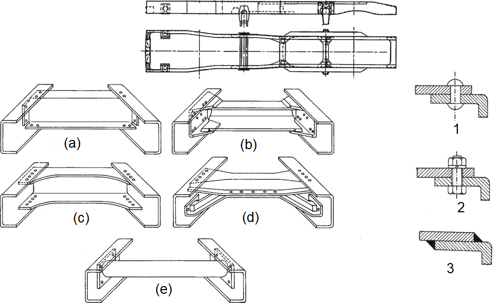 Different cross member connection types and reinforcement strategies.
Integral (Unibody/Monocoque)
An integral structure, also known as unibody or monocoque construction, is a structural system where the vehicle’s body panels and frame are combined into a single, unified structure. The term monocoque comes from French, meaning single shell.
The body panels serve as structural elements with no separate chassis frame. Compared with body-on-frame structures, the load is distributed through the entire structure rather than concentrated in a separate frame. Therefore, less weight is required to support the loads, which gives structural efficiency, i.e., better strength-to-weight ratio.
Historical Context
Origins : Developed in the aircraft industry during the early 1900s.
Automotive adoption : First used in mass production by Citroën Traction Avant (1934), Figure 1.4.
Modern evolution : Became standard for passenger cars by the 1960s.
 First mass-produced true integral car Citroën Traction Avant (1934).
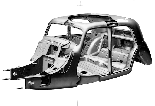
The Body-in-white Components
The Body-in-white (BIW) components are the main structural elements of a vehicle’s body, assembled before painting and the addition of trim or other components as shown in Figure 1.5. These components, typically made of sheet metal, include the roof, doors, fenders, floor pans, and pillars, forming the foundational structure of the car. The names of each component are shown in Table 1. The BIW stage is crucial because it determines the car’s overall shape, strength, and safety characteristics.
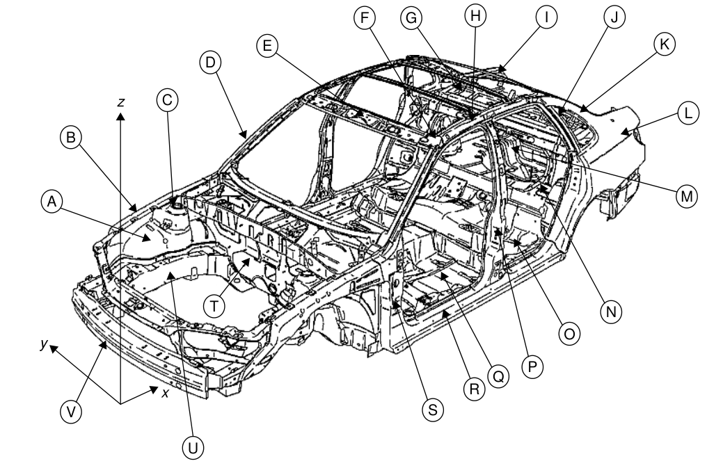
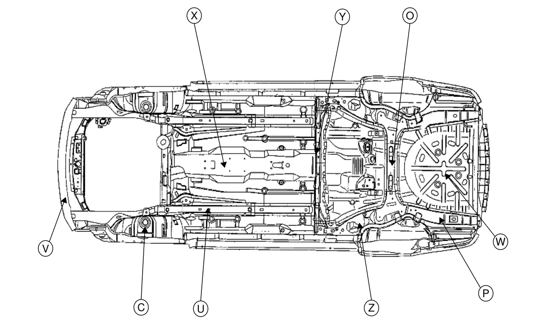
| BIW components. BIW component terminology {#tab:terminology} Item | UK Description | US Description |
|---|---|---|
| A | Inner wing panel | Motor compartment side panel |
| B | Upper wing member | Motor compartment upper rail |
| C | Suspension tower | Shock tower |
| D | Upper ‘A’-pillar | ‘A’-pillar or windshield pillar |
| E | Windscreen header rail | Windshield header or front header |
| F | Roof stiffener | Roof bow |
| G | Rear parcel tray | Package shelf |
| H | Cantrail | Side roof rail |
| I | Backlight frame | Backlite header or rear header |
| J | ‘C’-pillar | ‘C’-pillar |
| K | ‘D’-pillar | ‘D’-pillar |
| L | Rear quarter panel | Rear quarter panel |
| M | Boot floor panel | Rear compartment pan |
| N | Rear seatback ring | Rear seatback opening frame |
| O | Rear seat panel | Rear seatback panel |
| P | ‘B’-pillar | ‘B’-pillar or center pillar |
| Q | Floor panel | Floor pan |
| R | Sill | Rocker or rocker panel |
| S | Lower ‘A’-pillar | Front body hinge pillar (FBHP) |
| T | Dash panel | Dash panel |
| U | Engine (longitudinal) rail | Motor compartment lower rail |
| V | Front bumper | Front bumper |
| W | Spare wheel well | Spare tire well |
| X | Centre (longitudinal) tunnel | Tunnel |
| Y | Rear seat cross-beam | #4 crossbar |
| Z | Rear suspension support beam | #5 crossbar |
Construction and Manufacturing
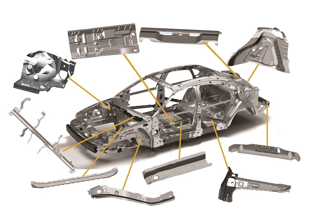
Integral or monocoque vehicle structures are constructed primarily from stamped sheet metal panels that are welded together to form a rigid, load-bearing body shell. The production process begins with the stamping of steel or aluminum sheets into precise body panels—such as floor pans, roof sections, side frames, and bulkheads—using large hydraulic or mechanical presses as shown in Figure 1.6. These panels are then assembled using a combination of spot welding, laser welding, and adhesive bonding to ensure structural integrity. Key structural elements, like longitudinal side rails, cross members, and pillars, are integrated into the design to distribute loads efficiently while maintaining lightweight properties. Robotic welding systems are commonly employed to achieve high precision and consistency in joining the complex geometries of monocoque structures as shown in Figure 1.7. Additional reinforcements, such as hydroformed tubes or tailored blanks (varying thickness sheets), may be incorporated in high-stress areas to enhance crashworthiness. The final assembly undergoes rigorous quality checks, including dimensional verification and weld integrity testing, before proceeding to painting and further component integration. This method eliminates the need for a separate chassis, reducing weight and improving structural efficiency, making it the preferred choice for modern passenger vehicles.
 Sheet Metal Body Parts.
 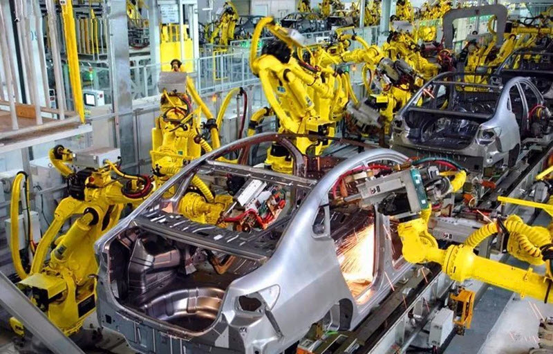 Automatic robots welding the structure.
Space Frame
A lightweight, high-strength structure made of interconnected tubular or extruded aluminum/steel members forming a three-dimensional framework, often covered with non-load-bearing panels. Unlike ladder frames (body-on-frame) or monocoque/unibody (integral) structures, space frames use a three-dimensional truss system to distribute loads efficiently.
Construction and Manufacturing
The space frame is made of primary frame of welded or bonded tubular sections forming a rigid 3D lattice and secondary non-structural outer panels (e.g., doors, fenders) made from lightweight materials and are joined together with the primary frame using mechanical fasteners (rivets or bolts).
Materials Used
Space frame construction utilizes various materials depending on performance requirements and era, including steel tubes (common in early designs), aluminum alloys (favored for weight reduction), carbon fiber reinforced polymers (CFRP for high-performance vehicles), and hybrid structures that combine metals with composite materials for optimized strength-to-weight characteristics.
Example Vehicles
Space frames are suited for special purpose vehicles with limited production volumes as shown in the following figures 1.8, 1.9, and 1.10:
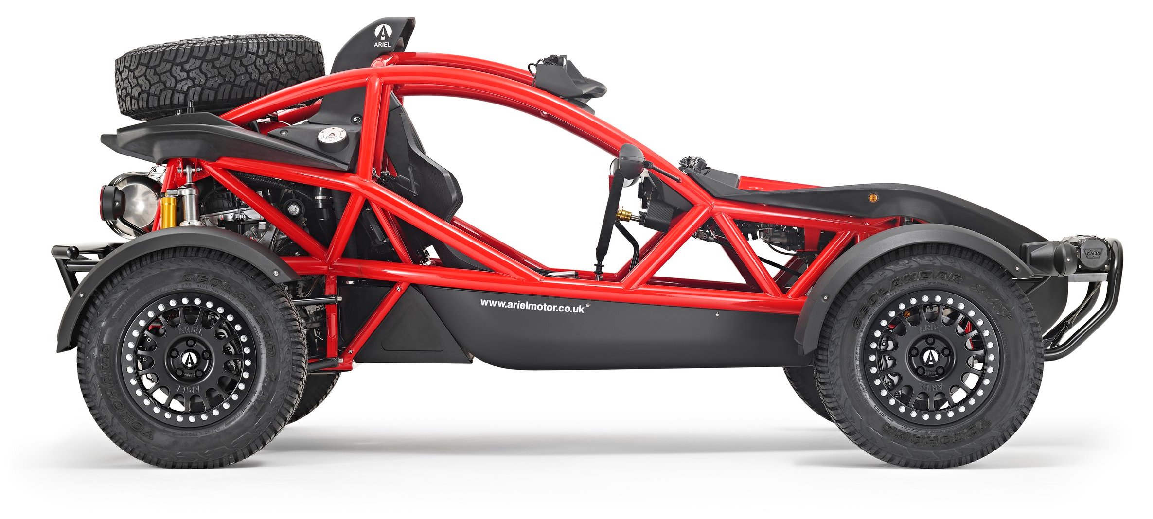 Ariel Nomad.
 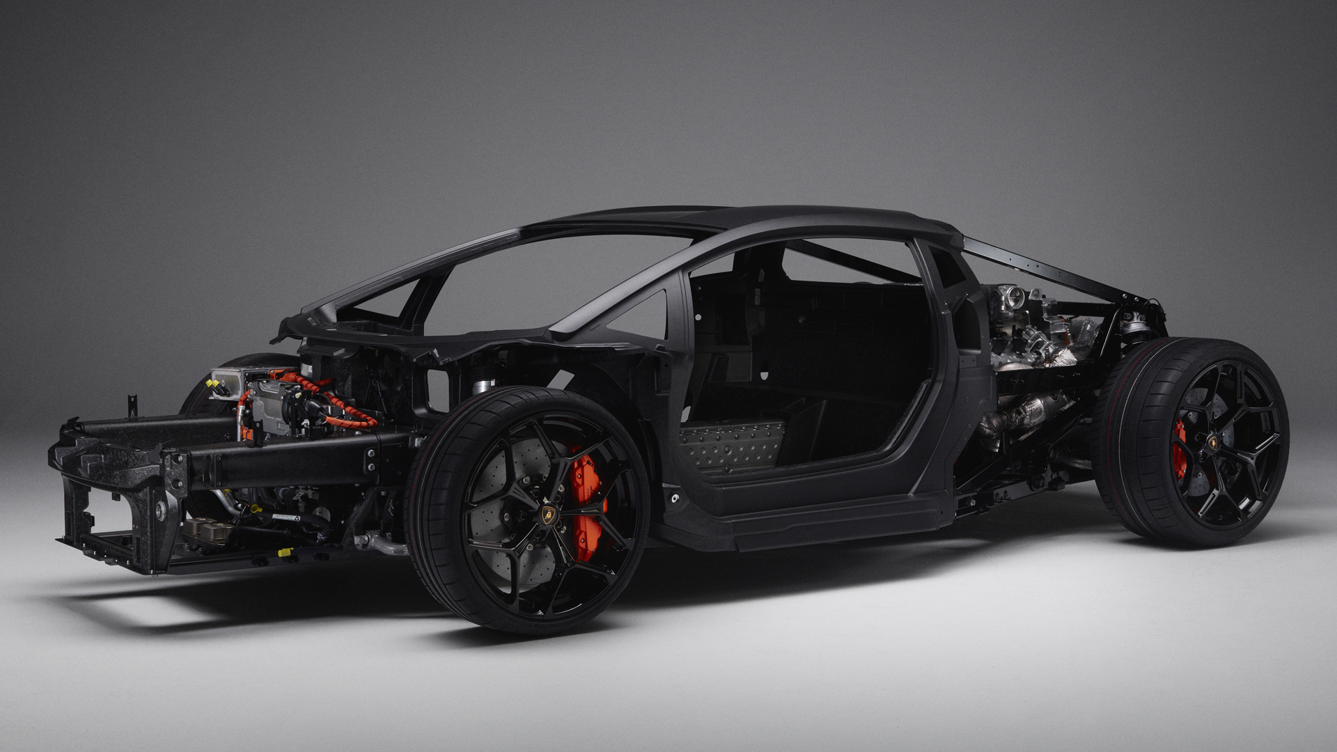 LB744: Lamborghini.
 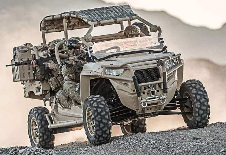 Military All-terrain vehicle ATV Polaris MRZR D4.
Backbone/Central Tunnel Structure
The backbone chassis is a vehicle frame design consisting of a strong central tubular structure that runs the length of the vehicle, connecting the front and rear suspension assemblies. Developed by Czechoslovakian company Tatra in the 1930s and later popularized by Lotus founder Colin Chapman, this design features a rigid central spine that provides exceptional torsional stiffness while remaining lightweight. The tubular backbone typically houses the drivetrain components and serves as the primary load-bearing structure, with front and rear subframes attached to support the suspension and powertrain.
This chassis design offers several advantages including excellent strength-to-weight ratio, simplicity of construction, and good handling characteristics due to its high torsional rigidity. It’s particularly well-suited for rear-wheel-drive sports cars, as demonstrated by classic Lotus models like the Elan and Esprit. The backbone design also allows for easy modification and body style changes since the outer body panels are non-structural. However, it provides less crash protection than unibody designs and can limit interior space due to the prominent central tunnel.
Modern applications of backbone chassis principles can be seen in some high-performance vehicles and kit cars, where the combination of lightweight construction and structural efficiency remains valuable. While largely superseded by monocoque designs for mass-produced vehicles, the backbone chassis continues to be used in specialized applications where its unique balance of simplicity, lightness, and stiffness is advantageous.
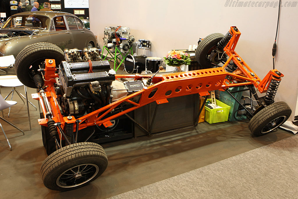
 Škoda Rahmen chassis.
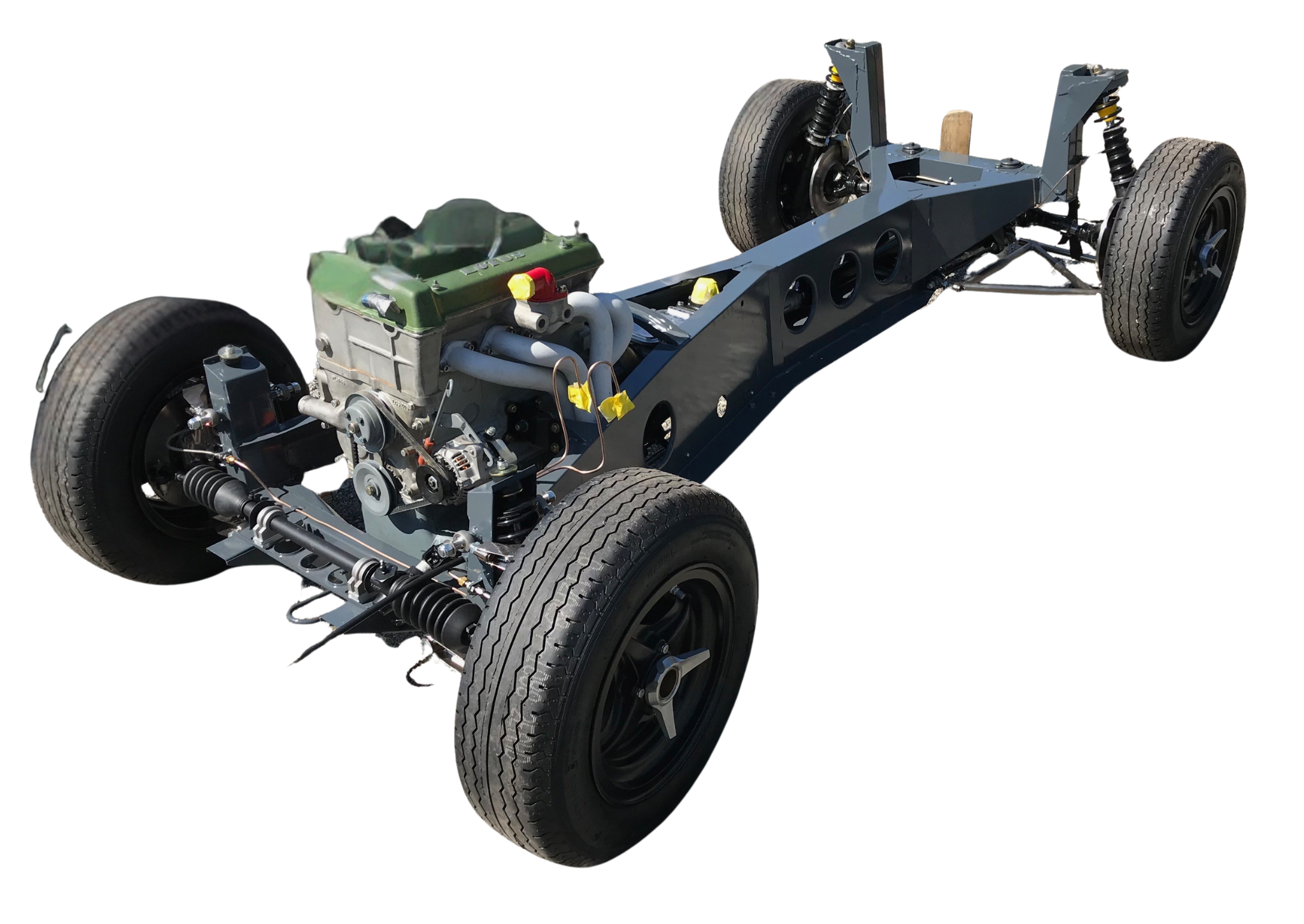
 Modern restoration using Lotus Elan chassis.
Construction and Manufacturing
Central Tunnel/Spine:
A reinforced box-section or tubular structure running the length of the vehicle. It houses drivetrain components (transmission, driveshaft) in rear-wheel-drive layouts. It provides mounting points for suspension and subframes.
Subframes:
Front and rear subframes attach to the central tunnel, supporting suspension and powertrain. They are often made from aluminum or steel for impact absorption.
Body Panels:
Non-structural outer panels (fenders, doors, roof) are bolted or bonded to the chassis. They are typically made from lightweight materials (aluminum, composites).
References
Malen, Donald E. 2011. Fundamentals of Automobile Body Structure Design. Warrendale: SAE International.