Design of Interior: Packaging and Ergonomics
Summary
This document outlines the concept of automotive packaging, defining it as the strategic process of locating and integrating all vehicle systems, components, occupants, and their cargo within the finite space of the vehicle. It emphasizes that packaging is fundamentally about space allocation to ensure all elements are accommodated in a way that satisfies customer expectations, functional requirements, and manufacturing constraints, effectively fitting disparate systems into a cohesive and functional whole. The discussion delves into occupant packaging, which focuses on the human-machine interface and defines the three-dimensional environment for occupants using Computer-Aided Design (CAD) models that incorporate key reference points, manikins, primary controls, and ergonomic zones.
Learning Objectives
Define automotive packaging and its core components within the vehicle design process.
Identify key reference points and standardized manikins used in human-centric occupant packaging.
Analyze the primary design considerations for vehicle interiors, including comfort, visibility, and storage.
Explain the iterative nature of the vehicle development sequence and ergonomic evaluations in packaging.
Interpret the standard vehicle coordinate system and specific SAE dimensional codes used to define interior dimensions.
Fundamentals of Vehicle Packaging
Definition
Packaging in the automotive context refers to the strategic process of locating and integrating all vehicle systems (e.g., powertrain, fuel system, climate control) and components, including the occupants and their cargo, within the finite space of the vehicle as shown in Figure 1.1. It is fundamentally about space allocation to ensure all hardware and occupants are accommodated in a way that satisfies customer expectations, functional requirements, and manufacturing constraints. The term aptly describes the task of fitting together disparate systems, often from various suppliers, into a cohesive and functional whole.
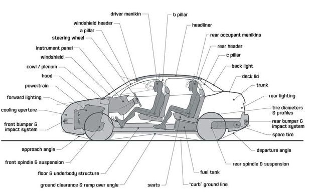 Anatomy of the passenger car package .
Occupant Packaging: The Human-Centric Core
Occupant packaging, or seating package layout, is the sub-discipline focused on the human-machine interface. It defines the three-dimensional environment for the driver and passengers. This is accomplished using Computer-Aided Design (CAD) models that incorporate:
Key Reference Points: Such as the Accelerator Heel Point (AHP) and the Seating Reference Point (SgRP).
Manikins: Digital representations of the human body based on SAE standards (e.g., J826, J4002) to simulate different body sizes (percentiles).
Primary Controls: Locations of the steering wheel, pedals, and gear shifter.
Ergonomic Zones: Including the driver’s eye locations (the “eyellipse” from SAE J941), head clearance contours, reach envelopes (e.g., Hand Reach, HR), and fields of view.
Figure 1.2 illustrates a typical side-view package drawing, integrating many of these critical ergonomic details.
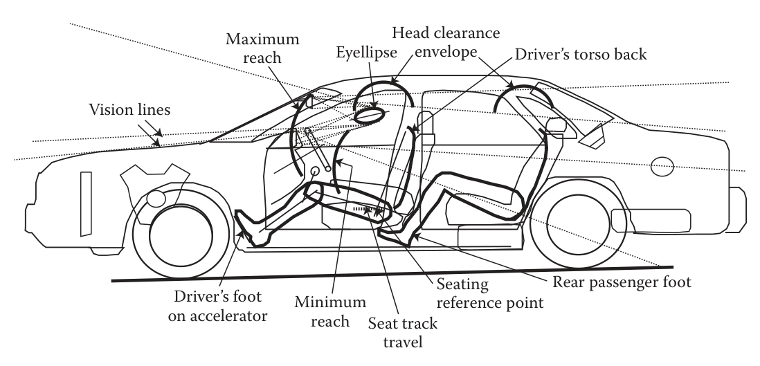 Illustration of a vehicle package layout. This diagram shows key ergonomic elements such as vision lines, reach envelopes, and the Seating Reference Point (SgRP) .
Key Design Considerations in Occupant Packaging
The development of a vehicle package involves a multitude of design considerations that balance comfort, convenience, and safety. These can be grouped into several key areas:
Entry and Egress Space: Location of seats, door opening size, and clearances for head, torso, and limbs during entry and exit.
Comfortable Seated Posture: Seat dimensions, support, and critical angles (torso, neck, knee, ankle) relative to controls.
Operating Controls: Logical placement of all controls and displays to allow for natural postures and minimal effort.
Visibility: Maximizing the driver’s view of the road and the vehicle’s interior displays while minimizing obstructions from pillars and other structures.
Storage Spaces: Providing convenient and safe cargo and personal item storage.
Vehicle Serviceability: Ensuring access for routine maintenance tasks like refueling, checking oil, and changing tires.
The Vehicle Development Sequence
The packaging process is iterative and integrated throughout the vehicle design stages, from early concept to production. The flow diagram in Figure 1.3 shows the interconnected tasks involved in occupant packaging and ergonomic evaluations.
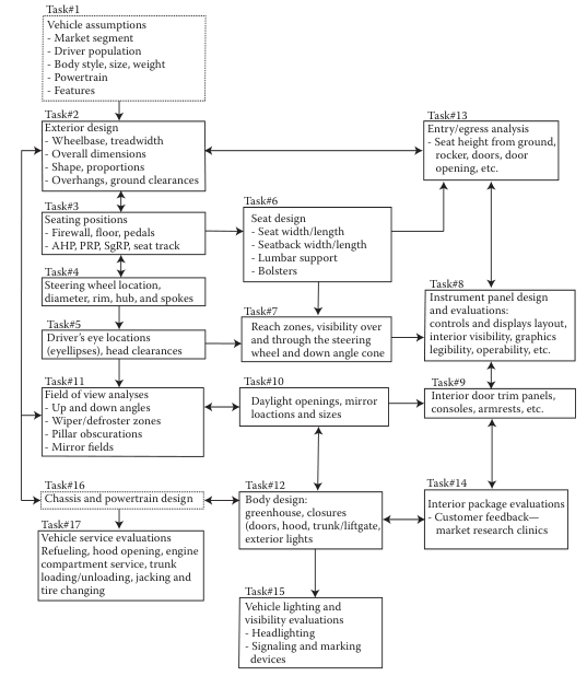 Flow diagram showing tasks involved in occupant packaging and ergonomic evaluations .
The process begins with market research and defining vehicle assumptions (Task 1) and flows through exterior design (Task 2), seating position (Task 3), and evaluations of controls, visibility, and interior components. This is a concurrent process where mechanical design (Task 12, 16) and ergonomic design are developed in parallel, with constant feedback loops (e.g., market research clinics, Task 14) to refine the design.
Key Vehicle Dimensions and Reference Points
Standardization is crucial for vehicle packaging. The SAE provides a comprehensive set of standards, primarily in SAE J1100, for defining dimensions and reference points. A summary of the acronyms is given in Table 1.
| Main Acronyms |
|
| AHP |
Accelerator Heel Point |
| BOF |
Ball of Foot |
| CAD |
Computer-Aided Design |
| G |
General Package Factor (for SAE reach calculations) |
| HPD |
H-Point Device (the modern SAE manikin fixture) |
| HPM |
H-Point Machine (the original SAE manikin fixture) |
| HR |
Hand Reach |
| OSCAR |
A common industry nickname for the H-Point Machine (HPM) |
| SAE |
Society of Automotive Engineers |
| SgRP |
Seating Reference Point |
| Prefixes |
|
| A |
Prefix for an angle dimension (e.g., A40 Torso Angle) |
| H |
Prefix for a vertical (height) dimension (e.g., H30 Seat Height) |
| L |
Prefix for a longitudinal (length) dimension (e.g., L53 AHP to SgRP) |
| W |
Prefix for a lateral (width) dimension (e.g., W3 Shoulder Room) |
| Dimension Codes |
|
| H11 |
Entrance Height |
| H13 |
Thigh Room (Steering Wheel to Thigh Line) |
| H61 |
Effective Headroom |
| L33 |
Leg Room |
| L62 |
Knee Clearance |
| W3 |
Shoulder Room |
| W5 |
Hip Room |
| W31 |
Elbow Room |
The Vehicle Coordinate System
A standard three-dimensional Cartesian coordinate system (as per SAE J182) is used Figure 1.4:
X-axis (Longitudinal): Positive direction pointing to the rear of the vehicle.
Z-axis (Vertical): Positive direction pointing upward from the ground.
Y-axis (Lateral): Positive direction pointing to the right side of the vehicle.
Body Zero: The origin (X=0, Y=0, Z=0) is typically located forward of the front bumper, below ground level, and on the vehicle centerline to ensure all coordinates are positive.
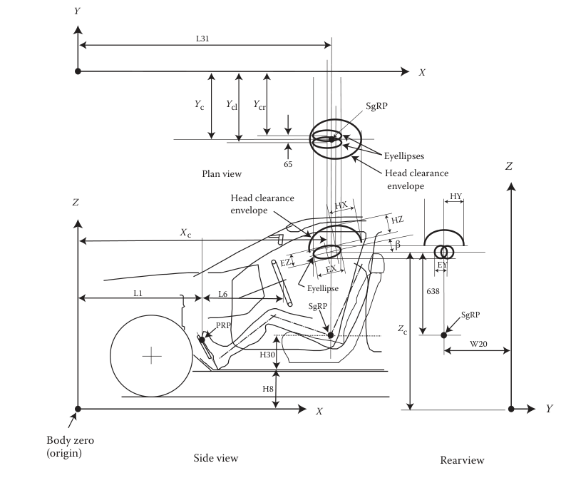 Vehicle Coordinate System .
Primary Interior Reference Points
The driver’s position is defined by a set of critical reference points shown in Figure 1.5.
Accelerator Heel Point (AHP): The pivot point of the driver’s foot on the floor when the shoe is on the undepressed accelerator pedal. It is the foundational point of the driver’s workspace.
Ball of Foot (BOF): The point on the driver’s foot that contacts the accelerator pedal, located 200 mm from the AHP along the pedal plane (SAE J4004).
Seating Reference Point (SgRP): The manufacturer-defined H-point (hip point) for a designated seating position, typically at the rearmost and lowermost position of seat travel. It is the most important reference point for defining the driver’s package.
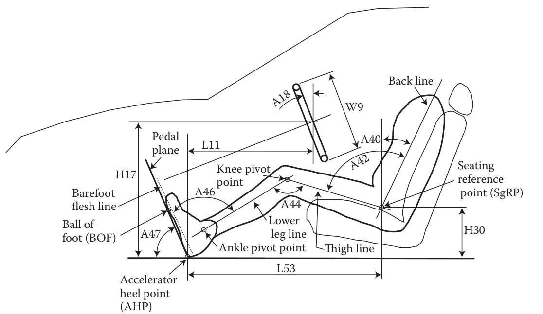 Interior package reference points and dimensions, including AHP, SgRP, and key posture angles .
Driver Package Development Procedures
Developing the driver package is a systematic process that uses established SAE procedures and formulas to accommodate a target driver population (e.g., 95% of drivers).
SAE H-Point Machine (HPM)
The location of the SgRP is physically verified using the SAE H-Point Machine (HPM), colloquially known as “OSCAR” (Figure 1.6). This is a 76 kg three-dimensional fixture that simulates a 50th percentile male, deflecting the seat cushions to provide a repeatable measurement of the actual H-point in a physical vehicle or buck. Table 1.1 shows a summary comparison of basic dimensions between 5th, 50th, and 95th percentile males.
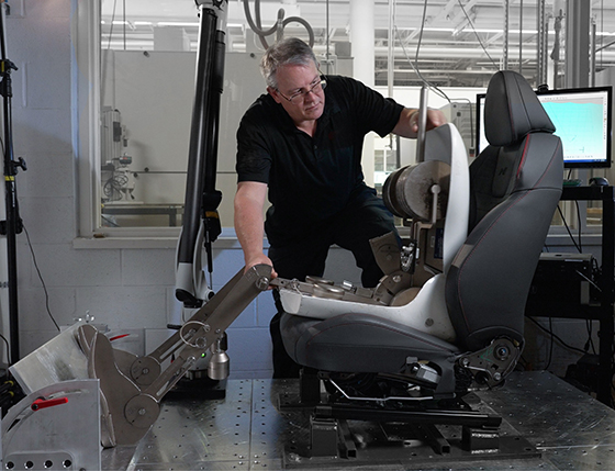 SAE H-point device (HPD or OSCAR), used to physically measure the H-point location in a seat. (Reproduced from ).
| Stature |
164.8 |
175.49 |
186.99 |
| Eye Height (Standing) |
153.59 |
164.01 |
175.31 |
| Shoulder Height (Standing) |
133.91 |
143.89 |
154.61 |
| Sitting Height |
86.0 |
91.8 |
97.69 |
| Sitting Eye Height |
75.01 |
80.39 |
86.0 |
| Sitting Shoulder Height |
55.19 |
60.3 |
65.3 |
| Sitting Elbow Height |
19.71 |
24.61 |
29.11 |
| Thigh Clearance |
15.7 |
18.01 |
20.7 |
| Buttock-Knee Length |
56.9 |
61.7 |
66.9 |
| Popliteal Height |
38.99 |
43.0 |
47.09 |
| Shoulder Breadth (Bideltoid) |
45.9 |
50.9 |
56.69 |
| Foot Length |
24.99 |
27.1 |
29.31 |
Key Interior Dimensions and Ergonomic Envelopes
Beyond seating position, a complete package defines numerous interior dimensions critical for comfort and safety. These are all measured relative to the SgRP and are defined in SAE J1100.
Roominess: Effective Headroom (H61, Figure 1.7), Legroom (L33, Figure 1.8), Shoulder Room (W3, Figure 1.9), Elbow Room (W31), and Hip Room (W5).
Clearances: Knee Clearance (L62), Thigh Room (H13, Figure 1.10), and Entrance Height (H11).
Visibility and Reach: Driver’s eyellipse, head clearance envelopes.
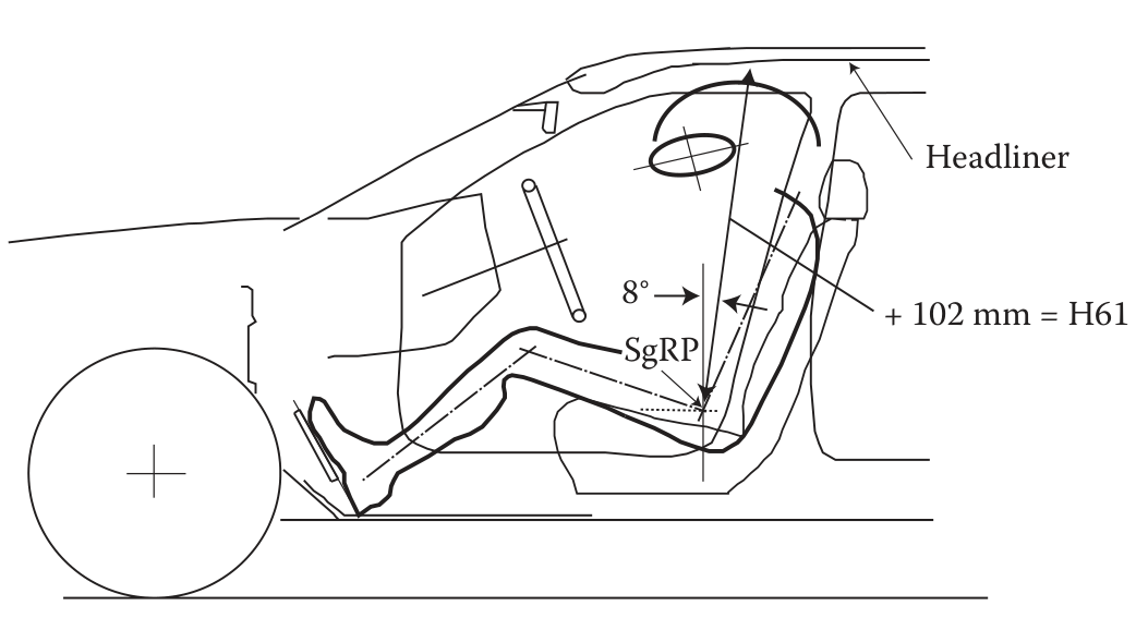 Effective Headroom (H61) measurement.
 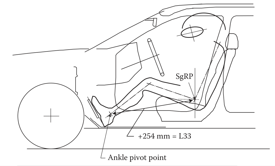 Legroom (L33) measurement.
 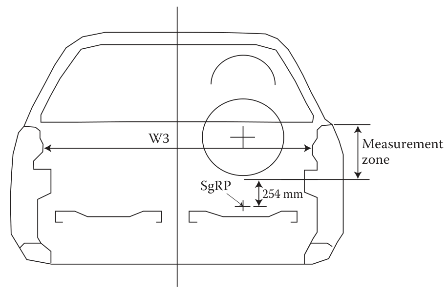 Shoulder Room (W3) measurement zone.
 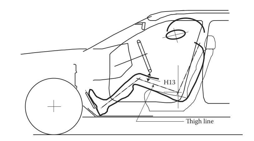 Thigh Room (H13), the clearance between the steering wheel and the thigh line.
The Eyellipse and Head Clearance Envelope
SAE J941 defines the eyellipse , a statistical 3D representation of the driver population’s eye locations. It is crucial for visibility studies (e.g., checking for A-pillar obstruction). Similarly, SAE J1052 defines the head clearance envelope , an ellipsoid representing the space occupied by the driver’s head, which must not interfere with the headliner or roof structure. Figure 1.4 shows the positioning of these envelopes relative to the SgRP.
Hand Reach Envelopes
SAE J287 provides data for maximum hand reach based on studies by (Hammond and Roe 1972) and others. This defines the outer boundary of where controls can be placed. The location of this reach surface is dependent on the vehicle type (via a “general package factor,” G), restraints used, and the target population.
Steering Wheel Location
The placement of the steering wheel is a critical compromise, constrained by:
Maximum Reach Envelope: Must be within reach of a small driver.
Minimum Reach Envelope: Must not be too close to a large driver.
Visibility: Must not obstruct the view of the instrument cluster or the road.
Thigh Clearance: Must allow for entry/egress and comfortable operation for a large driver.
References
Hammond, D. C., and R. W. Roe. 1972. “SAE Controls Reach Study.” Warrendale, PA: SAE International.