The Acoustic Signature of Failure#
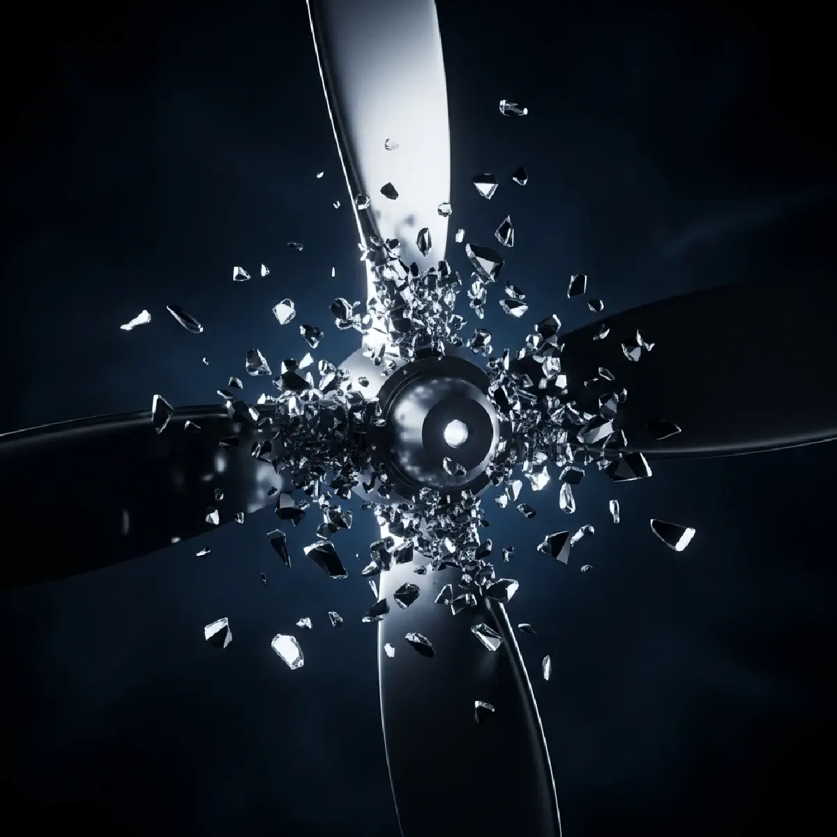
Reliability in turboprop aircraft depends on the structural integrity of the propeller assembly, which must withstand extreme centrifugal forces. On rare occasions, a crack in the propeller hub or blade leads to a catastrophic detachment known as blade loss. When a blade is lost, the engine begins to vibrate with sufficient power to threaten the airframe. For instance, a search and rescue helicopter crashed following the in-flight detachment of one of its five main rotor blades. In a similar case involving a Cessna 185 Skywagon, a propeller blade broke at one-third of its total length from the root. These events often begin with a small surface discontinuity that acts as a stress concentrator, leading to a rapid progression of metal fatigue.
The Mechanics of Unbalanced Momentum#
The physics of a spinning propeller dictate that any deviation in mass or surface quality results in non-linear dynamic responses. Failure analysis in these systems requires an understanding of how centrifugal loads interact with material flaws.
The Physics of Centrifugal Imbalance#
A propeller blade moves through a helical path, generating thrust while resisting centripetal forces. When a blade detaches, the rotary forces follow the equations where the lateral force (Fy) is a function of the centrifugal force (Fc) and the rotational frequency (ω). The loss of a blade introduces an instantaneous imbalance that must be absorbed by the engine mounting system (EMS). The EMS is designed to act as a mechanical fuse, potentially detaching the engine to prevent fatal structural damage to the wing or fuselage. This dynamic response is highly dependent on the angular position of the blade at the moment of loss and the flexibility of the wing structure.
The Evolution of the Fracture Zone#
In the Cessna 185 failure, the 2024 aluminum alloy blade displayed two distinct fracture zones. Zone-I was located at the leading edge and was perpendicular to the longitudinal axis, showing smooth surfaces and fatigue striations. Zone-II showed a dull, dimpled appearance characteristic of a ductile fracture under monotonic loading. The fatigue striations in Zone-I originated from a surface dent that was 140 μm (0.0055 in) deep and 3060 μm (0.12 in) wide. This dent acted as a notch, increasing local stresses and initiating microcracks. Once the crack reached a critical size, the remaining cross-section could no longer support the operating loads, leading to the final ductile rupture.
The Limitation of Surface Inspections#
The forensic investigation of the Cessna blade revealed a significant oversight in the maintenance cycle. The blade had been inspected just 50 flight hours prior to the accident using fluorescent penetrant inspection (FPI). SEM analysis showed that the critical dent was covered by a layer of paint. Measurements identified that the paint thickness on the dent was 112 μm (0.0044 in), compared to 50 μm (0.0019 in) on the surrounding surface. This indicated that the dent had formed before the last inspection, and the paint had pooled within the depression during the subsequent refinishing. The FPI failed to detect the flaw because the paint layer was flexible enough to deform without cracking, effectively masking the structural breach from the inspector.
The Design for Dynamic Tolerance#
The prevention of blade-loss accidents requires the integration of better non-destructive testing (NDT) and revised manufacturing procedures. For the helicopter spar failure, investigators recommended the adoption of X-ray inspections every 200 flight hours to supplement the In-flight Blade Inspection System (IBIS). In the case of turbine gear failures, it was concluded that unauthorized grinding operations led to thermal damage and grinding cracks. Designers must ensure that sharp fillets and radii are eliminated, as high-stress concentration factors are the primary drivers of fatigue crack nucleation. By increasing the radius of curvature at critical junctions and strictly adhering to processing specifications, the aerospace industry can mitigate the risks inherent in high-speed rotational components.